Connector pin definition specifies the electrical function of every contact in a charger interface, using an identified connector and an unambiguous drawing view. In an OEM charger project, matching the plug shape is only the mechanical starting point. Power polarity, auxiliary signals and the vehicle-side wiring must also agree before a sample can be approved.
For vehicle manufacturers, battery brands and importers, a missing pin definition can turn a straightforward repeat order into an incompatible spare. This guide explains what to put on the interface drawing, how to resolve extra contacts and how to carry the approved mapping into production. It does not provide a universal charger wiring diagram.

What Plug Fit Does and Does Not Confirm
Two cable assemblies may fit the same inlet while connecting its contacts to different electrical functions. A physical match does not establish positive and negative output, permission to charge, communication compatibility or a suitable current and voltage rating. Define these as separate approval questions.
| What you have checked | What remains to be confirmed | Useful evidence |
|---|---|---|
| The plug fits the vehicle inlet. | Contact functions, polarity, ratings and control requirements. | Identified mating parts and an approved pin map. |
| The main positive and negative contacts match. | Every remaining contact and the conditions for enabling charge. | Battery or vehicle interface specification. |
| The connector has an adequate current rating. | Voltage suitability, cable and termination limits, and operating conditions. | Exact component data and assembled-system evaluation. |
| A sample charges the intended battery. | Whether its drawing, cable build and production test reference the same revision. | Sample record linked to a controlled cable specification. |
Linjia’s custom battery charger development process includes connector, cable and polarity requirements. Supply the interface information while the configuration is being reviewed; postponing it until packing leaves engineering and production to work around an unresolved requirement.
Define the Connector and Drawing View Before Numbering Pins
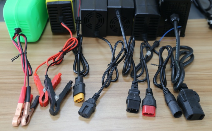
Start with the connector manufacturer and exact part number, including the contact insert, coding and mating part where applicable. Identify whether the drawing describes the charger cable, vehicle inlet or battery harness. A family name, contact count or informal description such as “three-pin plug” leaves important details open.
Then state the viewing direction. A drawing looking into the mating face and a drawing looking at the wire-entry or termination side can show the contacts in reversed positions. The contact number remains attached to the same physical contact when the view changes. Do not renumber contacts simply to keep numbers reading left to right.
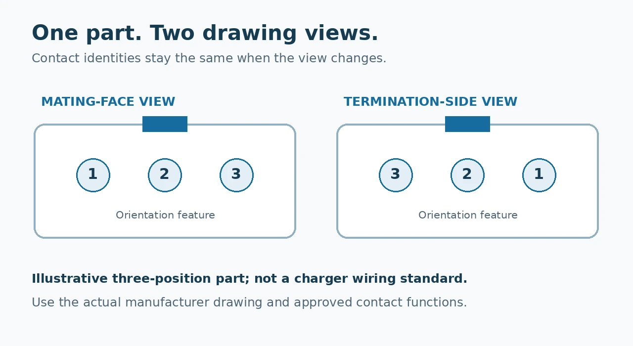
Mark a visible orientation feature, such as the key, latch or locating notch, and label the side being shown. For example, a project drawing might state: charger cable connector, mating-face view, latch at the top. That sentence still needs the identified part and its manufacturer’s numbering; it is not a substitute for them.
Manufacturer drawings illustrate this discipline. Phoenix Contact’s 1522613 cable documentation distinguishes a socket-face contact arrangement from the associated wire-to-contact assignment. Its particular wiring belongs to that component, rather than to battery chargers in general.
Specify Power Contacts and Auxiliary Contacts Separately
For the charging-power circuit, identify the actual contact carrying positive output and the contact carrying its return. Record any separate shield or shell connection explicitly. Do not treat DC negative, a signal reference, chassis and protective earth as interchangeable names; their relationship must come from the approved system design.
Wire colors can help an assembler follow an approved drawing, but color alone does not establish the function at the mating face. Record the contact number, electrical function and wire identification together. The vehicle or battery supplier must confirm the corresponding destination on its side.
An extra contact is an unanswered question until documented
A third contact might be unused in one design and carry an enable, interlock, identification or temperature-related function in another. More complex interfaces may carry communication signals. Contact count cannot identify which arrangement applies, and an extra contact does not prove that a charger supports any particular communication function.
Obtain the signal specification when a signal is required: its reference, permitted levels, input or output role and the behavior expected during connection, charge permission and a fault. A communication requirement also needs the applicable protocol and compatibility criteria. Do not bridge an unknown contact to a power contact or copy an online pinout to make a charger start.
For an industry example, the MEAN WELL NPB-450 datasheet documents a model-specific control connector with distinct remote-control, status and communication functions. This illustrates why auxiliary contacts need their own definitions; those features and assignments must not be assumed for a Linjia model.
Pin definition does not establish connector suitability
Correct polarity cannot compensate for an unsuitable connector or cable assembly. Review the exact contacts, working voltage, permitted current, conductor specification, termination method, strain relief and environmental conditions. Use the actual charging-voltage requirement when assessing voltage suitability, rather than the battery’s nominal class alone.
Neutrik’s NC3FXX product data, for example, specifies current and voltage ratings separately. An acceptable current figure by itself therefore does not establish suitability for a charger project. This is a component-documentation example, not a recommendation to use that connector.
Build One Interface Approval Record for Both Sides
The useful deliverable is a record that purchasing, the cable assembler, the vehicle team and quality staff can all interpret the same way. Keep the following fields together. Populate them from the actual project documents; unresolved functions should remain open items that block compatibility approval.
| Field | What the project record should contain |
|---|---|
| Interface identity | Project and charger variant, cable-assembly number, connector and mating-part identification. |
| Drawing convention | Charger or vehicle side, mating-face or termination-side view, orientation feature and manufacturer’s contact numbering. |
| Each contact | Contact identifier, approved function, wire identifier and corresponding vehicle/battery connection. |
| Signal conditions | Required signal reference, levels, logic or protocol, and the charge-permission sequence where applicable. |
| Unused positions | Whether the cavity is empty or a fitted contact is deliberately unconnected; any required insulation or sealing treatment. |
| Cable and component limits | Approved contacts, conductors, cable length, ratings, termination and installation requirements. |
| Acceptance and revision | Sample identifier, drawing revision, verification scope, approval responsibility and effective order or batch. |
A per-contact schedule can use the columns contact ID → function → wire ID → mating destination → verification requirement. Fill one row for every position. Avoid a note such as “same as sample” without an identified sample and supporting drawing.
Keep interface approval connected to the wider battery requirements. The battery charger selection guide covers the broader matching task, and seven specifications to confirm before ordering a custom charger provides the order-level checklist. A fully documented connector still needs the correct charging profile, voltage and current.
Verify the Sample Through the Intended Mating Interface
Have the responsible technical teams compare the sample cable and actual mating interface against the drawing. The agreed evaluation should cover mechanical fit and retention, contact mapping and polarity, required control behavior, and charging operation with the intended battery or vehicle. Include relevant cable-routing and connection-temperature checks under the project’s approved conditions.
Use qualified personnel, suitable equipment and the manufacturers’ procedures for electrical verification. Do not use a live battery as a trial-and-error pin-identification tool. Reverse-polarity protection, if provided on a particular model, is not a substitute for resolving an unknown interface.
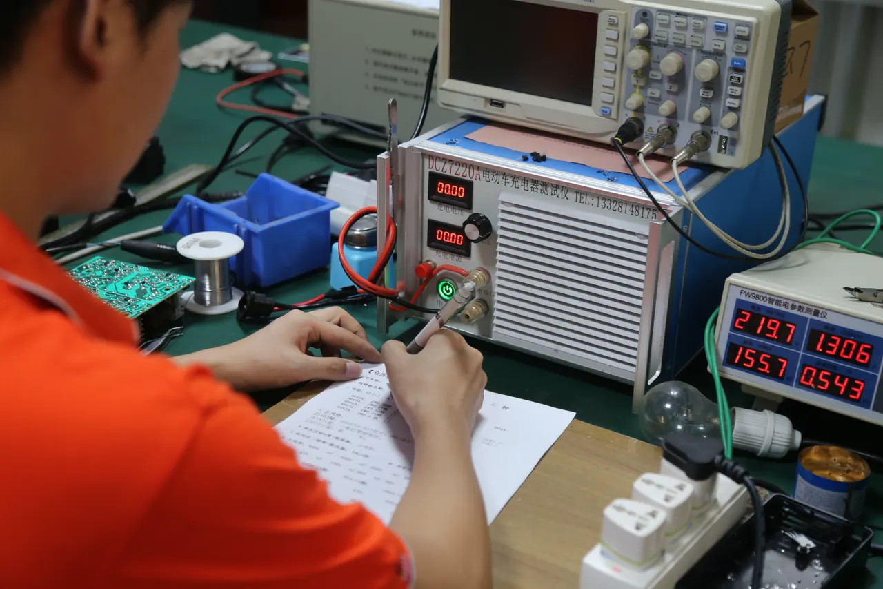
The test fixture needs the same revision as the cable drawing
A production test checks the connections presented to its fixture. If an adapter routes an incorrectly wired plug to the expected tester terminals, a successful load test alone can miss the customer-side mismatch. This is a test-design risk to review, not a claim about a recorded Linjia failure.
Identify the fixture’s mating part and mapping in the test instructions. Agree how contact assignment and polarity are verified at the customer-facing interface, as well as what the functional load test covers. A new connector, supplier, adapter or signal arrangement should trigger a review of the affected drawings and checks.
Linjia’s charger quality-control process includes electrical checks and full-load burn-in. Those checks need an agreed configuration to verify; burn-in alone does not establish that every contact matches a particular vehicle. Keep the approved interface revision with the production reference described in our guide to sample approval and mass-production consistency.
Buyer Checklist Before Releasing an OEM Charger Interface
- Identify the cable-side connector and actual vehicle or battery mating part.
- Approve a numbered drawing with a named view and clear orientation.
- Define every power, signal, shell and unused position without relying on color alone.
- Resolve ratings, cable construction and any BMS or vehicle control requirements.
- Evaluate the identified sample through the intended interface and record the conditions.
- Link the drawing, sample, fixture and order to the same approved revision.
Frequently Asked Questions
Is a clear connector photograph enough for a quotation?
It can support an initial discussion, especially when paired with a part number. A firm interface proposal still needs the contact functions and mating information. If identification remains uncertain, provide a labelled physical mating sample for technical review.
Can an unused third contact simply be connected to negative?
No. Leave its function unresolved until the responsible system designer confirms it. A contact that is unused in one project may perform a control function in another, and an unintended connection can create an incompatible or damaging interface.
Does the same connector part number guarantee charger compatibility?
No. It helps establish component identity, but the cable wiring, charging profile, ratings and control behavior still require approval. Distributors should tie service spares to approved vehicle and battery combinations.
Can an adapter solve a pin-assignment difference?
Only as an engineered and approved assembly with a defined mapping, suitable ratings and verified control behavior. Treat it as part of the charging path and spare-parts specification, rather than an informal workaround.
Send Your Connector Definition for an OEM Charger Review
Send Linjia Power clear connector and inlet photos, available part numbers, a numbered pin drawing with its viewing direction, cable requirements and any vehicle or BMS interface document. Include the battery chemistry, charging-voltage specification, permitted current, application and order quantity.
Mark unknown contacts and accepted sample revisions explicitly. Our team can use that information to review the proposed charger configuration and identify what must be resolved before sampling or production.
Technical References
Primary manufacturer documents checked on October 24, 2026: Phoenix Contact 1522613 cable documentation (contact-view and assignment drawings); MEAN WELL NPB-450 datasheet, revision dated July 6, 2026 (model-specific control functions); Neutrik NC3FXX product data (separate electrical ratings). Links appear beside the relevant explanations. External component and charger examples do not establish approval or supported functions for a Linjia product.