Battery capacity tells you how large a charging current is relative to the pack; the BMS charge current limit helps define whether that current is permitted. Neither an Ah label nor a BMS headline rating approves a charger on its own. For lithium packs, distinguish the battery maker’s operating limit, the BMS continuous charge rating, any changing charge-current request, and the protection trip threshold. The charger must operate within the applicable limits and use the correct voltage and charging profile.
This guide focuses on Li-ion and LiFePO4 battery projects. It explains how to read the capacity and BMS information behind a current specification. For the wider vehicle, connector and charging-window decision, see our 48V charging-current selection guide.

Capacity changes the C-rate of a given current
Amp-hours describe charge capacity under specified conditions. Amps describe the current flowing at a particular moment. Their relationship can be expressed as C-rate = charging current (A) ÷ rated battery capacity (Ah). The same 10A current therefore represents a different relative charging rate for different packs.
| Rated pack capacity | Illustrative charger current | Calculated charge rate |
|---|---|---|
| 20Ah | 10A | 0.5C |
| 40Ah | 10A | 0.25C |
| 100Ah | 10A | 0.1C |
The calculation compares rates; it does not tell you which rate the cells or assembled battery allow. Two packs with identical Ah ratings can use different cells, thermal designs and charging rules. A manufacturer’s recommended charge rate can also be lower than its maximum continuous rating. Victron’s Lithium Battery Smart operating manual, for example, distinguishes its recommended current from its maximum rating. That product-specific recommendation must not be transferred to unrelated batteries.
More cells do not always mean more Ah or more permitted current
For identical cells in an idealized pack, series connections add voltage while the Ah capacity stays that of one parallel group. Parallel connections add Ah capacity. If each cell is rated at 5Ah, a 4P group has a nominal 20Ah capacity; adding more of those groups in series changes pack voltage, not that 20Ah figure.
This arithmetic does not approve a higher-current charger. The assembled pack still needs an approved charge-current specification covering its cell selection, interconnections, protection hardware, charging port and heat dissipation. Increasing the parallel cell count while retaining the same charge-path hardware may leave the permitted current unchanged.
Also separate parallel cells within an engineered pack from connecting complete battery packs in parallel. The latter introduces additional sharing and protection questions and requires the battery manufacturer’s approved system design. A capacity calculation is not an instruction to rewire batteries.
Read the BMS charge current limit separately from three other figures
A purchase specification that says only “30A BMS” is incomplete. Ask what the number describes, which port it applies to, and under what temperature and cooling conditions it is valid.
| Figure or setting | What it describes | What the charger buyer must obtain |
|---|---|---|
| Continuous charge-current rating | The charge path’s permitted continuous operating current under stated conditions | The charge rating for the actual BMS, pack and charging port |
| Discharge-current rating | Current delivered from the battery to a load | A separate charge-current approval; a large discharge number does not supply it |
| Charge-overcurrent protection threshold | A fault-detection level, often combined with a delay and recovery rule | Threshold tolerances, delay and recovery behavior, separately from the normal operating limit |
| Dynamic charge current limit (CCL) | A current request that a compatible BMS can change during operation | Control method, message definition, units, timing and required stop behavior |
Protection operation is not evidence of an acceptable normal charging current. Texas Instruments’ bq40z60 reference manual describes charge-overcurrent thresholds and delays separately from discharge protection. This illustrates why “it did not trip during a short test” cannot establish a continuous rating. The actual thresholds and timing must come from the specific pack’s configuration, not from another controller’s defaults. See the TI reference manual, section 2.5.
Balancing current is another separate specification. It concerns cell equalization and should not be mistaken for the current that the complete charging path can accept.
A BMS may stop charging, request less current, or do both
A disconnecting BMS does not automatically regulate charger output
Some battery systems permit charging until a protection or enable condition opens the charging path. That switching action does not turn an oversized fixed-output charger into an approved lower-current model. Specify a charger current that the pack permits during normal operation, together with the required end-of-charge and fault response.
A communicating system needs an agreed control interface
Other systems communicate a changing CCL to a compatible charger. The request may decrease as temperature or individual cell voltage approaches a limit, and it may become zero. The charger and system controller must enforce the requested behavior. Orion’s BMS wiring manual, pages 13–14, describes CAN, analog and on/off control methods and explains the need for an external means of enforcing its limits.
For such a project, ask the battery and charger suppliers to agree what happens at startup, when the limit falls, when charging is disabled, and when valid communication is lost. Record the required response time and the test that proves it. A CAN connector or an extra pin alone does not establish protocol compatibility.
Do not treat a temporary stop as permission to repeatedly reconnect or bypass the BMS. Identify the reason for the stop and resolve any fault before resuming the approved charging process.
Check actual maximum output, including tolerance
The useful procurement question is whether the charger’s delivered current stays inside the approved operating envelope. Comparing two nominal labels is insufficient when either device has a tolerance or a temperature-dependent limit.
Illustrative calculation, not a Linjia model specification: assume a 40Ah pack has written approval for 10A at the agreed conditions, while its BMS charging path permits 8A continuously. Assume all other charging-path limits exceed 8A. A candidate charger has an 8A nominal setting with a hypothetical +5% upper tolerance. Its calculated upper output is 8 × 1.05 = 8.4A, so that specification exceeds the 8A continuous limit.
A hypothetical 6A setting with the same tolerance gives 6.3A and passes that particular arithmetic check. It still needs validation of voltage, profile, temperature, transient behavior and the complete interface. If the battery later requests a lower dynamic limit, that request also has to be respected. The amount of design margin is a project decision; there is no universal percentage that approves every combination.
The engineering consequence is practical: put the permitted output range and its test conditions on the approved charger specification. An overcurrent trip threshold should not be used as extra normal operating headroom.

Keep the battery revision tied to the charger approval
Linjia’s published customization process reviews battery capacity, charging current, full-charge voltage and BMS requirements before confirming a configuration. Its product platforms provide a starting point for an engineering discussion. For a project in that voltage class, our 48V lithium battery charger platforms show the available catalogue context; they do not approve an unspecified battery.
From a manufacturing perspective, the important control is the approved combination. A replacement cell, different parallel arrangement, revised BMS firmware or changed charging port may require a new compatibility review even if the sales label still shows the same voltage and Ah.
Record the pack part number and revision, the BMS configuration, the charger output range, and the interface definition together. Sample acceptance should include the charge-current envelope and required BMS stop or reduction behavior. Routine electrical checks and burn-in have different purposes; neither alone proves the whole battery-control interface. Our charger quality-control process describes the production checks supporting the approved configuration.
What to request before confirming a charging current
- Pack approval: chemistry, cell configuration, rated Ah, exact charging voltage and recommended/maximum current across the intended operating conditions.
- BMS definitions: continuous charge rating, separate discharge rating, charge-overcurrent settings, temperature rules, and any dynamic CCL behavior.
- Charger behavior: output-current tolerance, applicable derating, termination, enable/disable response and communication requirements where relevant.
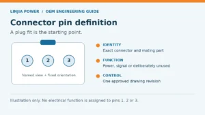
- Interface evidence: the charging-port and cable ratings, polarity, power and signal pin definitions, plus the approved drawing revision.
- Acceptance record: the exact battery/BMS/charger revisions, agreed test conditions, results and the changes that require reapproval.
Will a larger-capacity battery make a charger deliver more current?
Not by capacity alone. A fixed-current charger normally retains its configured current limit when operating in its constant-current region. A different battery may change how long that region lasts. Current can also be lower because of voltage regulation, pack requests, temperature or other operating conditions.
Can replacing the BMS authorize faster charging?
Not on its own. A different BMS may change one constraint, while the cells, interconnections, thermal design and charging port retain their previous limits. Obtain a revised approval for the assembled battery rather than transferring a BMS headline rating to the whole pack.
Does a lower measured capacity on an aging battery define a new current setting?
No. Reduced capacity is a condition to investigate, not a complete charging specification. Resistance, cell imbalance and temperature behavior may also have changed. Follow the pack supplier’s service and charging instructions; do not calculate a new approved setting from remaining Ah alone.
Send the limits, not just the Ah label
For a charger review, send the battery datasheet and revision, BMS charge limits and control requirements, target current, full-charge voltage, connector drawing, AC input, operating environment and quantity. Include the proposed current tolerance and acceptance criteria if already defined. Send Linjia your battery and BMS specifications so the charger configuration can be evaluated against the actual pack.